| Обновлено 2020-04-29 10:33:20 |
|
Слесарно-монтажный ручной инструмент / Hand tools GEDORE | Каталог GEDORE 2014 Слесарный инструмент (Всего 670 стр.) |
|||||
433 Каталог GEDORE 2014 Профессиональный слесарный инструмент и оборудование Стр.431 |
|||||
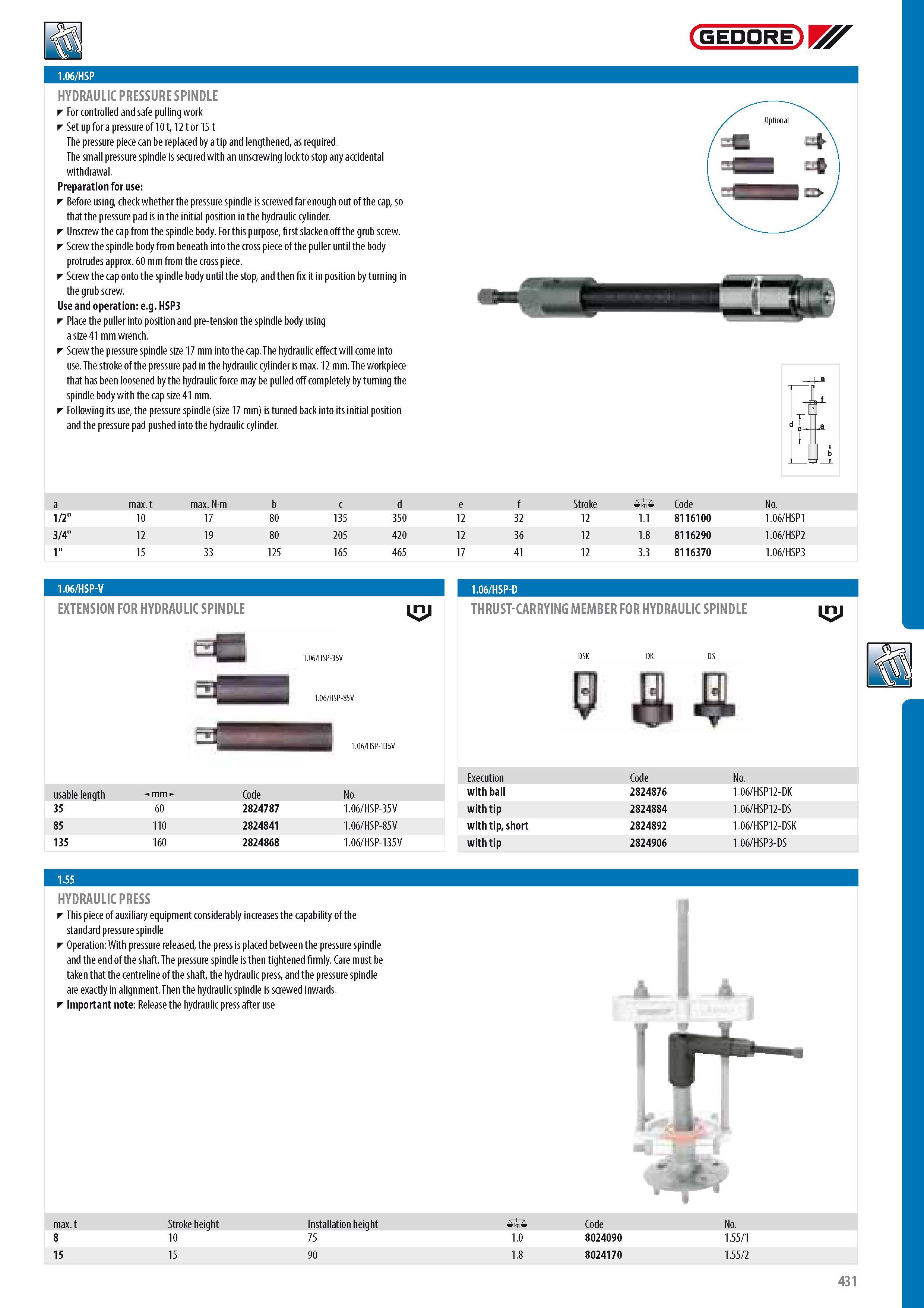
Каталог GEDORE 2014 Слесарный инструмент Стр. 431 0433 ENG Lab2u GEDORE HYDRAULIC PRESSURE SPINDLE For controlled and safe pulling work Set up for a pressure of 10 12 or 15 The pressure piece can be replaced by a tip and lengthened as required. The small pressure spindle is secured with an unscrewing lock to stop any accidental withdrawal. Preparation for use Before using check whether the pressure spindle is screwed far enough out of the cap so that the pressure pad is in the initial position in the hydraulic cylinder. Unscrew the cap from the spindle body. For this purpose first slacken off the grub screw. Screw the spindle body from beneath into the cross piece of the puller until the body protrudes approx. 60 mm from the cross piece. Screw the cap onto the spindle body until the stop and then fix it in position by turning in the grub screw. Use and operation e.g. HSP3 Place the puller into position and pre-tension the spindle body using a size 41 mm wrench. Screw the pressure spindle size 17 mm into the cap. The hydraulic effect will come into use. The stroke of the pressure pad in the hydraulic cylinder is max. 12 mm. The workpiece that has been loosened by the hydraulic force may be pulled off completely by turning the spindle body with the cap size 41 mm. Following its use the pressure spindle (size 17 mm) is turned back into its initial position and the pressure pad pushed into the hydraulic cylinder. dI 1 a max. max. Nm b c d e f Stroke 0 Code No. 1 2" 10 17 80 135 350 12 32 12 1.1 8116100 1.06 HSP1 3 4" 12 19 80 205 420 12 36 12 1.8 8116290 1.06 HSP2 1" 15 33 125 165 465 17 41 12 3.3 8116370 1.06 HSP3 1.06 HSP-V EXTENSION FOR HYDRAULIC SPINDLE 1.06 HSP-D G THRUST-CARRYING MEMBER FOR HYDRAULIC SPINDLE G Execution Code No. usable length m mm mi Code No. with ball 2824876 1.06 HSP12-DK 35 60 2824787 1.06 HSP-35V with tip 2824884 1.06 HSP12-DS 85 110 2824841 1.06 HSP-85V with tip short 2824892 1.06 HSP12-DSK 135 160 2824868 1.06 HSP-135V with tip 2824906 1.06 HSP3-DS HYDRAULIC PRESS T his piece of auxiliary equipment considerably increases the capability of the standard pressure spindle Operation With pressure released the press is placed between the pressure spindle and the end of the shaft. The pressure spindle is then tightened firmly. Care must be taken that the centreline of the shaft the hydraulic press and the pressure spindle are exactly in alignment. Then the hydraulic spindle is screwed inwards. Important note Release the hydraulic press after use max. Stroke height Installation height 0 Code No. 8 10 75 1.0 8024090 1.55 1 15 15 90 1.8 8024170 1.55 2 1.06 HSP 1.55 431 |
|||||
См.также / See also : |
|||||
Отклонения размеров / Fit tolerance table |
Соотношение твердостей Таблица / Hardness equivalent table |
||||
Типы резьб / Thread types and applications |
Аналоги сталей / Workpiece material conversion table |
||||
Отверстия под резьбу / Tap drill sizes |
Обороты в скорость / Surface speed to RPM conversion |
||||
Перевод дюймов в мм / Inches to mm Conversion table |
Перевод единиц в систему СИ / SI unit conversion table |
||||
| |
|||||
| GEDORE | |||||
| |
|||||
 Каталог GEDORE 2016 Ручной инструмент и оборудование (676 страниц) |
|||||
 Каталог GEDORE 2014 Слесарный инструмент (англ.яз.) (670 страниц) |
|||||
 Каталог GEDORE 2012 Инструмент (692 страницы) |
 Каталог GEDORE 2006 Слесарно- монтажный инструмент (англ.яз.) (298 страниц) |
||||
| |
|||||
|
Каталоги ручного инструмента / Hand tools catalogs |
|||||
| Каталог GEDORE 2014 Слесарный инструмент (Всего 670 стр.) | |||||
| |
|||||
 430 430 |  431 431 |  432 432 | 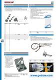 434 434 |  435 435 |  436 436 |
|
Lab2U | Catalogs | Tap drill sizes | Speed to RPM | Material table Разработчики сайта / Developers of site |
|
Поиск на сайте Lab2u.ru с помощью поисковых систем ЯНДЕКС, BING, GOOGLE:
|
||
|
|
||
