| Обновлено 2020-04-14 09:50:57 |
|
Металлорежущий инструмент и инструментальная оснастка / Cutting tools and tooling system KENNAMETAL | Каталог KENNAMETAL 2013 Инструментальная оснастка для станков (Всего 1575 стр.) |
|||||
1412 Каталог KENNAMETAL 2013 Инструментальная оснастка для металлорежущих станков Стр.M12 |
|||||
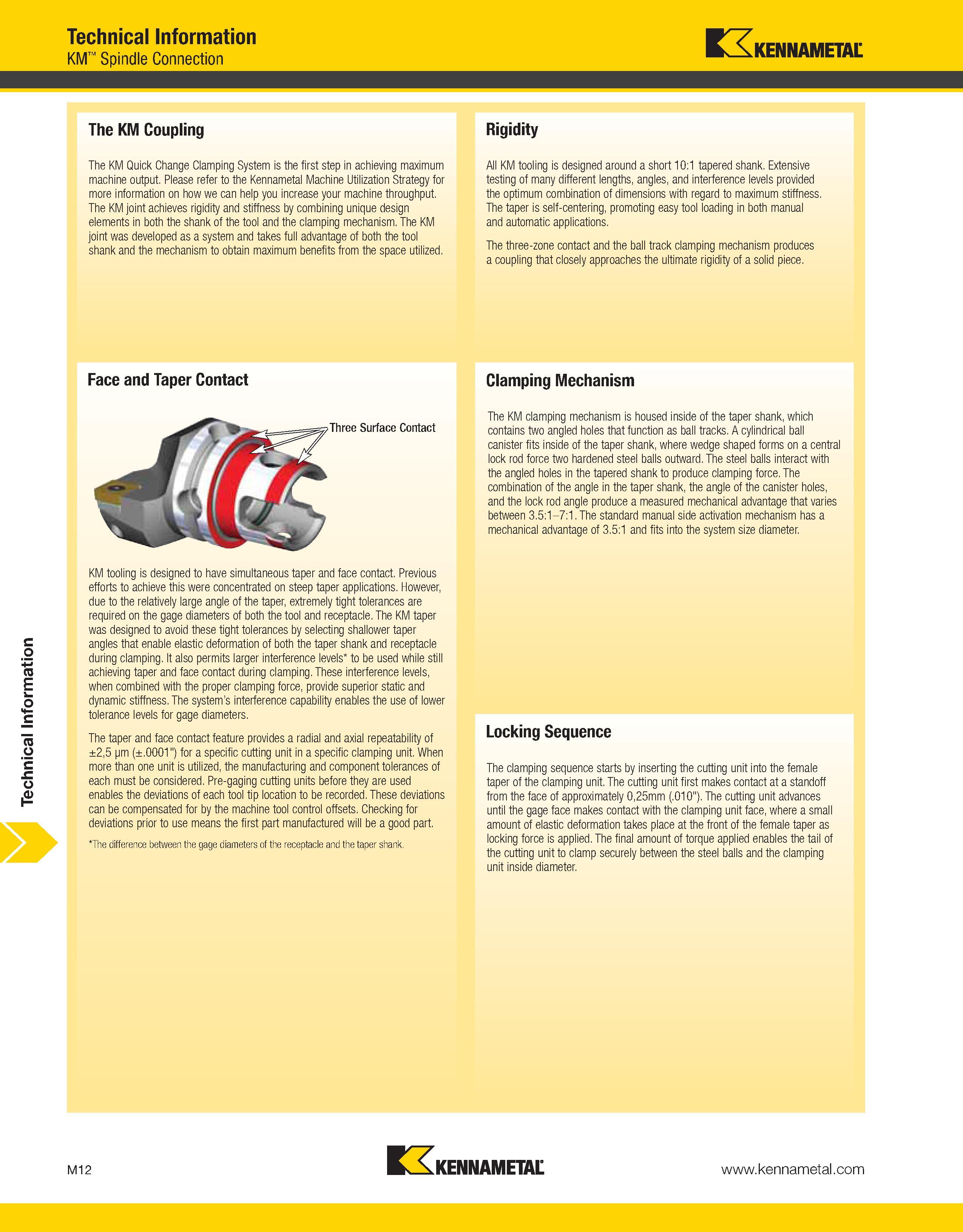
Каталог KENNAMETAL 2013 Инструментальная оснастка Стр. M12 1412 Lab2u Technical Information Technical Information KM Spindle Connection Kennametal The KM Coupling The KM Quick Change Clamping System is the first step in achieving maximum machine output. Please refer to the Kennametal Machine Utilization Strategy for more information on how we can help you increase your machine throughput. The KM joint achieves rigidity and stiffness by combining unique design elements in both the shank of the tool and the clamping mechanism. The KM joint was developed as a system and takes full advantage of both the tool shank and the mechanism to obtain maximum benefits from the space utilized. Face and Taper Contact KM tooling is designed to have simultaneous taper and face contact. Previous efforts to achieve this were concentrated on steep taper applications. However, due to the relatively large angle of the taper, extremely tight tolerances are required on the gage diameters of both the tool and receptacle. The KM taper was designed to avoid these tight tolerances by selecting shallower taper angles that enable elastic deformation of both the taper shank and receptacle during clamping. It also permits larger interference levels to be used while still achieving taper and face contact during clamping. These interference levels, when combined with the proper clamping force, provide superior static and dynamic stiffness. The system’s interference capability enables the use of lower tolerance levels for gage diameters. The taper and face contact feature provides a radial and axial repeatability of ±2,5 pm (±.0001") for a specific cutting unit in a specific clamping unit. When more than one unit is utilized, the manufacturing and component tolerances of each must be considered. Pre-gaging cutting units before they are used enables the deviations of each tool tip location to be recorded. These deviations can be compensated for by the machine tool control offsets. Checking for deviations prior to use means the first part manufactured will be a good part. The difference between the gage diameters of the receptacle and the taper shank. Rigidity All KM tooling is designed around a short 10:1 tapered shank. Extensive testing of many different lengths, angles, and interference levels provided the optimum combination of dimensions with regard to maximum stiffness. The taper is self-centering, promoting easy tool loading in both manual and automatic applications. The three-zone contact and the ball track clamping mechanism produces a coupling that closely approaches the ultimate rigidity of a solid piece. Clamping Mechanism The KM clamping mechanism is housed inside of the taper shank, which contains two angled holes that function as ball tracks. A cylindrical ball canister fits inside of the taper shank, where wedge shaped forms on a central lock rod force two hardened steel balls outward. The steel balls interact with the angled holes in the tapered shank to produce clamping force. The combination of the angle in the taper shank, the angle of the canister holes, and the lock rod angle produce a measured mechanical advantage that varies between 3.5:1-7:1. The standard manual side activation mechanism has a mechanical advantage of 3.5:1 and fits into the system size diameter. Locking Sequence The clamping sequence starts by inserting the cutting unit into the female taper of the clamping unit. The cutting unit first makes contact at a standoff from the face of approximately 0,25mm (.010"). The cutting unit advances until the gage face makes contact with the clamping unit face, where a small amount of elastic deformation takes place at the front of the female taper as locking force is applied. The final amount of torque applied enables the tail of the cutting unit to clamp securely between the steel balls and the clamping unit inside diameter. M12 Kennametal |
|||||
См.также / See also : |
|||||
Металлообработка Учебники и справочники / Metal Cutting Technology Technical Guide |
Особенности сверления металла / Drill a hole in metal |
||||
Токарная обработка металла / Basics of metal turning |
Фрезерование на фрезерном станке / Basics of milling |
||||
Нарезание резьбы метчиками / Tapping |
Развертывание отверстий и развертки по металлу / Reaming and reamer cutting tool |
||||
Расточка на токарном станке / Boring on a lathe |
Растачивание отверстий на расточном станке / Boring on a boring machine |
||||
| |
|||||
| KENNAMETAL | |||||
| |
|||||
 Каталог KENNAMETAL 2018 Инструмент токарный (988 страниц) |
 Каталог KENNAMETAL 2018 Инструменты вращающиеся для станков (1920 страниц) |
||||
 Каталог KENNAMETAL 2017 Новый режущий инструмент и оснастка (524 страницы) |
 Каталог KENNAMETAL 2016 Новый инструмент и оснастка (324 страницы) |
 Каталог KENNAMETAL 2015 Инновации (260 страниц) |
 Каталог KENNAMETAL 2014 Новый инструмент и оснастка (630 страниц) |
 Каталог KENNAMETAL 2013 Металлорежущий инструмент (2130 страниц) |
 Каталог KENNAMETAL 2013 Инструментальная оснастка для станков (англ.яз / ENG) (1575 страниц) |
 Каталог KENNAMETAL 2007 Системы инструмента (844 страниц) |
 Каталог KENNAMETAL 2004 Режущий инструмент для точения (535 страниц) |
||||
| |
|||||
|
Каталоги инструмента и оснастки для металлообработки на станках / Cutting tools and tooling system catalogs |
|||||
| Каталог KENNAMETAL 2013 Инструментальная оснастка для станков (Всего 1575 стр.) | |||||
| |
|||||
 1409 1409 |  1410 1410 |  1411 1411 | 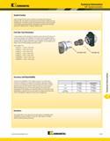 1413 1413 |  1414 1414 |  1415 1415 |
|
Lab2U | Catalogs | Tap drill sizes | Speed to RPM | Material table Разработчики сайта / Developers of site |
|
Поиск на сайте Lab2u.ru с помощью поисковых систем ЯНДЕКС, BING, GOOGLE:
|
||
|
|
||
