| Обновлено 2020-04-12 18:38:23 |
|
Металлорежущий инструмент и инструментальная оснастка для станков INGERSOLL | Каталог INGERSOLL 2011 Инструмент и оснастка (Всего 1440 стр.) |
|||||
312 Каталог INGERSOLL 2011 Режущий инструмент и инструментальная оснастка Стр.314 |
|||||
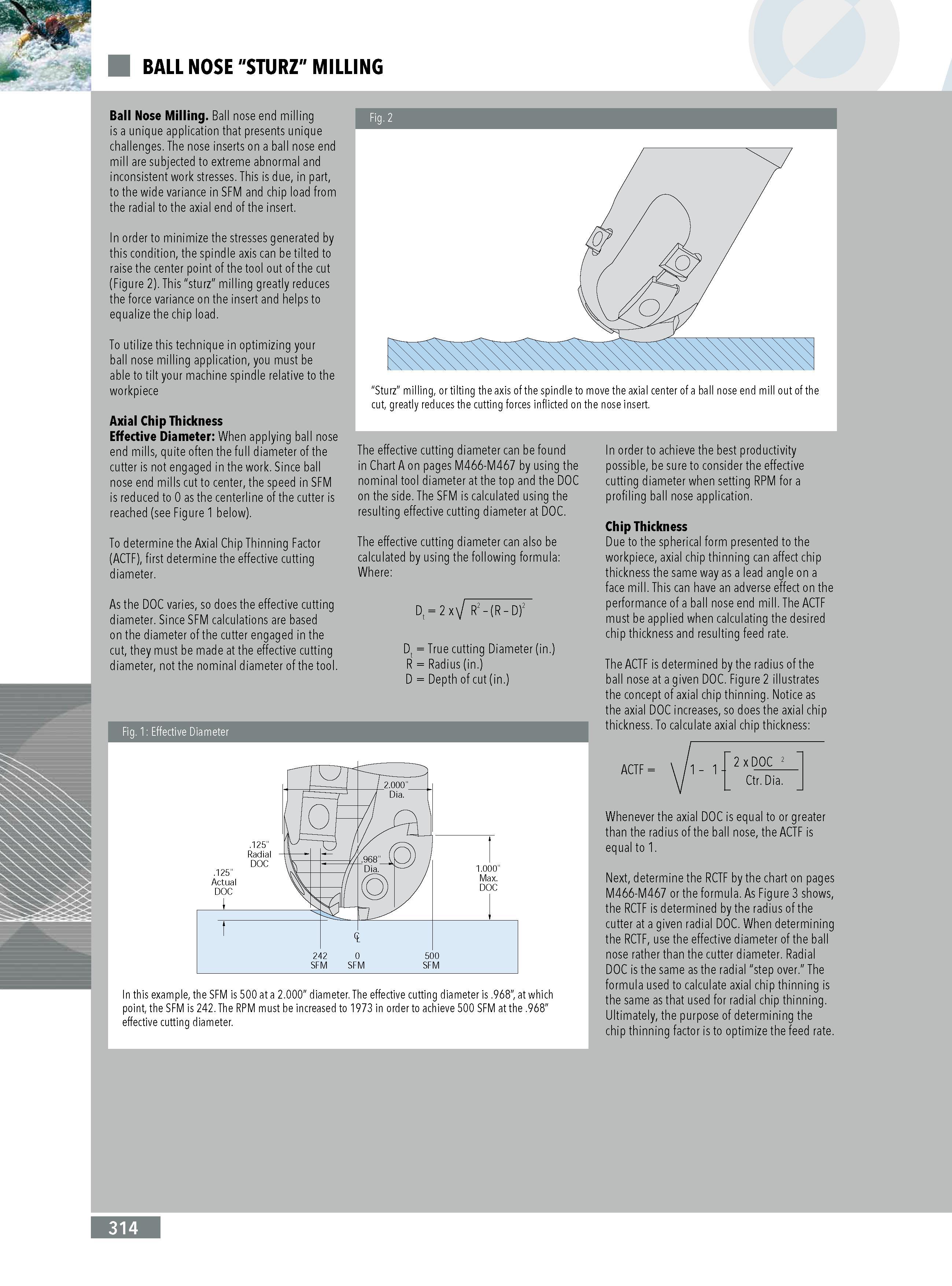
Каталог INGERSOLL 2011 Инструмент и оснастка Стр. 314 0312 Lab2u BALL NOSE "STURZ" MILLING Ball Nose Milling. Ball nose end milling is a unique application that presents unique challenges. The nose inserts on a ball nose end mill are subjected to extreme abnormal and inconsistent work stresses. This is due in part to the wide variance in SFM and chip load from the radial to the axial end of the insert. In order to minimize the stresses generated by this condition the spindle axis can be tilted to raise the center point of the tool out of the cut (Figure 2). This "sturz milling greatly reduces the force variance on the insert and helps to equalize the chip load. To utilize this technique in optimizing your ball nose milling application you must be able to tilt your machine spindle relative to the workpiece Axial Chip Thickness Effective Diameter: When applying ball nose end mills quite often the full diameter of the cutter is not engaged in the work. Since ball nose end mills cut to center the speed in SFM is reduced to 0 as the centerline of the cutter is reached (see Figure 1 below). To determine the Axial Chip Thinning Factor (ACTF) first determine the effective cutting diameter. As the DOC varies so does the effective cutting diameter. Since SFM calculations are based on the diameter of the cutter engaged in the cut they must be made at the effective cutting diameter not the nominal diameter of the tool. Fig. 1: Effective Diameter "Sturz milling or tilting the axis of the spindle to move the axial center of a ball nose end mill out of the cut greatly reduces the cutting forces inflicted on the nose insert. The effective cutting diameter can be found in Chart A on pages M466-M467 by using the nominal tool diameter at the top and the DOC on the side. The SFM is calculated using the resulting effective cutting diameter at DOC. The effective cutting diameter can also be calculated by using the following formula: Where: Dt 2 x j R2 - (R - D)2 Dt True cutting Diameter (in.) R Radius (in.) D Depth of cut (in.) In order to achieve the best productivity possible be sure to consider the effective cutting diameter when setting RPM for a profiling ball nose application. Chip Thickness Due to the spherical form presented to the workpiece axial chip thinning can affect chip thickness the same way as a lead angle on a face mill. This can have an adverse effect on the performance of a ball nose end mill. The ACTF must be applied when calculating the desired chip thickness and resulting feed rate. The ACTF is determined by the radius of the ball nose at a given DOC. Figure 2 illustrates the concept of axial chip thinning. Notice as the axial DOC increases so does the axial chip thickness. To calculate axial chip thickness: In this example the SFM is 500 at a 2.000 diameter. The effective cutting diameter is .968 at which point the SFM is 242. The RPM must be increased to 1973 in order to achieve 500 SFM at the .968 effective cutting diameter. 1 - 1 - "2xDOC 2Ctr. Dia. ACTF Whenever the axial DOC is equal to or greater than the radius of the ball nose the ACTF is equal to 1. Next determine the RCTF by the chart on pages M466-M467 or the formula. As Figure 3 shows the RCTF is determined by the radius of the cutter at a given radial DOC. When determining the RCTF use the effective diameter of the ball nose rather than the cutter diameter. Radial DOC is the same as the radial "step over. The formula used to calculate axial chip thinning is the same as that used for radial chip thinning. Ultimately the purpose of determining the chip thinning factor is to optimize the feed rate. Fig. 2 314 |
|||||
См.также / See also : |
|||||
Соотношение твердостей Таблица / Hardness equivalent table |
Аналоги марок стали / Workpiece material conversion table |
||||
Отклонение размера детали / Fit tolerance table |
Перевод оборотов в скорость / Surface speed to RPM conversion |
||||
Диаметр под резьбу / Tap drill sizes |
Виды резьбы в машиностроении / Thread types and applications |
||||
Дюймы в мм Таблица / Inches to mm Conversion table |
Современные инструментальные материалы / Cutting tool materials |
||||
| |
|||||
| INGERSOLL | |||||
| |
|||||
 Каталог INGERSOLL 2016 Инструмент фрезерный и сверлильный (нем.яз. / DEU) (616 страниц) |
 Каталог INGERSOLL 2015 Токарный инструмент (ENG FRA) (560 страниц) |
||||
 Каталог INGERSOLL 2014 Фрезерный инструмент (668 страниц) |
|||||
 Каталог INGERSOLL 2011 Инструмент и оснастка (англ. яз. / ENG) (1440 страниц) |
|||||
| |
|||||
|
Каталоги инструмента и оснастки для металлообработки на станках / Cutting tools and tooling system catalogs |
|||||
| Каталог INGERSOLL 2011 Инструмент и оснастка (Всего 1440 стр.) | |||||
| |
|||||
 309 309 |  310 310 |  311 311 |  313 313 |  314 314 |  315 315 |
|
Lab2U | Catalogs | Tap drill sizes | Speed to RPM | Material table Разработчики сайта / Developers of site |
|
Поиск на сайте Lab2u.ru с помощью поисковых систем ЯНДЕКС, BING, GOOGLE:
|
||
|
|
||
